How it came about
In January 2011, my father, Fred Connacher, was contacted by Etta
Albright of Cresson, about building a model of the Cresson Sanatorium which treated and cared for over 40,000 tuberculosis
patients from 1913 to 1964. It was hoped the model would be available for the upcoming 100th anniversary reunion
which was to be held in August.
Over the years, dad has actively worked to preserve the history of the community of
Cresson through historical models, renderings and railroad paintings. However, at 88 years of age, he wasn’t sure he
wanted to tackle a project of this magnitude especially considering the reunion deadline. I offered whatever help I could
give should he decide to build the model.
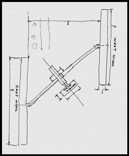
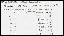
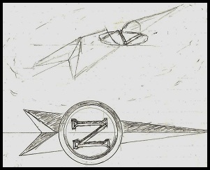
The very evening dad received the call from Etta, I was dad’s guest
at an appreciation dinner hosted by the Cresson Heritage Days Association. Before the meal was served, I looked across the
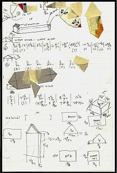
table and noticed that dad was drawing on his napkin. The seed had been planted and ever the artist, dad was doing a rough
sketch of the main structures of the san layout from memory. I knew there would be no stopping him!
Preliminary
work
In order for dad to begin the preliminary layout of the facility on paper before beginning the actual
construction, he needed blueprints of the layout and building plans. My role was launched as researcher for information on
the facility. Fortunately, during my research, I came across Chuck Felton’s website which offered a wealth of information.
I sent an email to Chuck explaining about the model and asked if he had knowledge of existing blueprints. Unfortunately, Chuck
had previously tried to locate them without success because of the loss of some of the PA State files in Harrisburg due to
flooding from hurricane Agnes in 1972. What also made it difficult to locate blueprints is the fact that the san facility
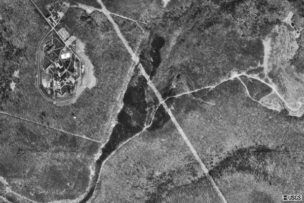
was a continual work-in-progress over the years of its operation. However, as always throughout the project, Chuck offered
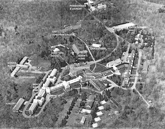
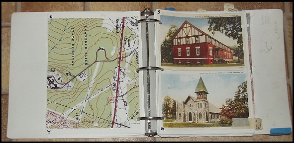
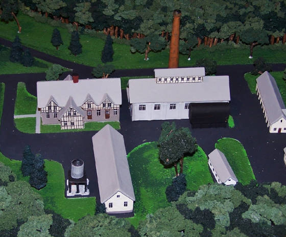
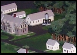
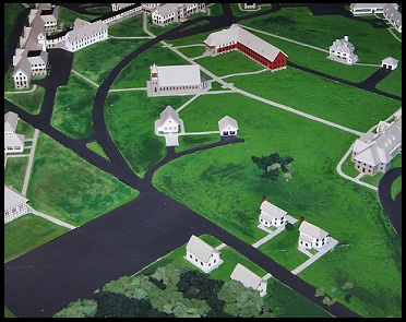
his assistance and sent several aerial view photographs from different perspectives taken of the facility in 1960. These,
as well as the USGS maps on Chuck’s website, proved invaluable to dad when laying out the facility, positioning
buildings and in their individual design.
As much detail was needed to scale and construct the buildings, I continued
researching.
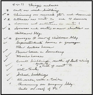
I found old PA Department of Health Journals documenting the san’s early years and various
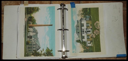
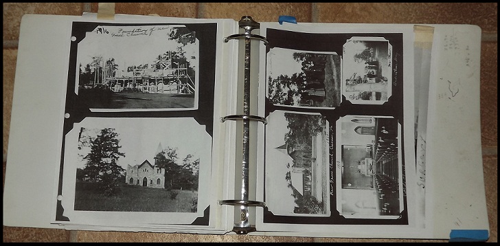
other publications which provided additional information. Also, with Chuck’s permission, I copied, enlarged and printed
all the photos relevant to the building designs from his website which dad put into a loose-leaf binder for reference. These
photos were another invaluable aid and Dad spent many hours studying them to identify individual building details.
It
didn’t escape us that these photos were more than a means to identify the architectural design of the various buildings.
Dad has always attempted to create his models with the men and women in mind who are at the heart of the subject being depicted.
The Cresson san model was no different. The stories and photos shared on Chuck’s website breathed “life”
into the model building process and became a motivational factor in our effort to have it completed in time for the planned
reunion. A huge undertaking considering August was less than seven months away!
Determining
the scale
In the early stages, a scale for the model had to be determined. Since the san facility was spread
over a large area and there were so many buildings, dad knew he had to keep the scale small in order to keep the size of the
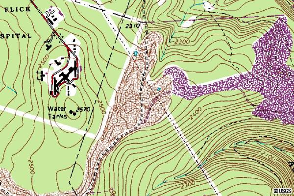
finished display reasonable. To accomplish this, dad studied the old USGS maps on Chuck’s website which showed
the location of the sanatorium buildings and their relative location to other features in the area such as the main highway,
streams, etc. Dad chose not to represent the topographical features on the model which would have slowed the process considerably.
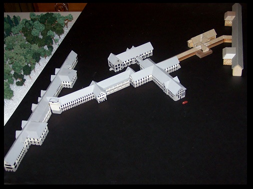
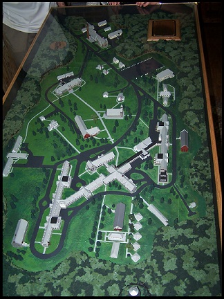
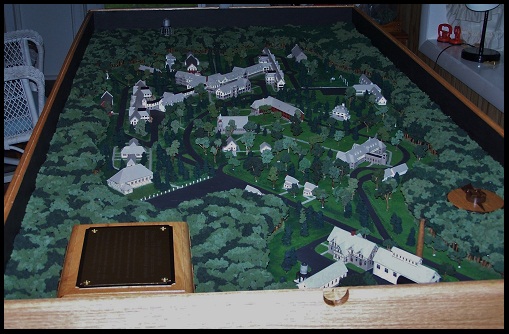
Using the scale on the USGS map, dad determined that by going with a 1/32 inch-per-foot scale he could build
the model 6¢ long by 3¢ wide which would adequately cover
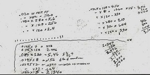
the area needed to represent the facility. In holding the length to 6¢ it was necessary for
dad to reduce the actual scale distance between the south end of the West Wing and the center of the water tower (a wooded
area) to be sure to have the water tower landmark included. Dad informed me from his computations that a scale of 1/32 inch-per-foot
on a 6¢ model is 2,304 feet (.44 miles) and that 3 feet would be 1,152 (.22miles) for a total
of .095 square miles. It was these types of computations that left my head spinning and glad dad was the man in charge! And
so began this representation of the PA State TB Sanatorium at Cresson, nearly 100 years after the completion of the first
buildings constructed to treat tuberculosis patients at this facility on the summit of Cresson mountain.
Laying
out the design on paper
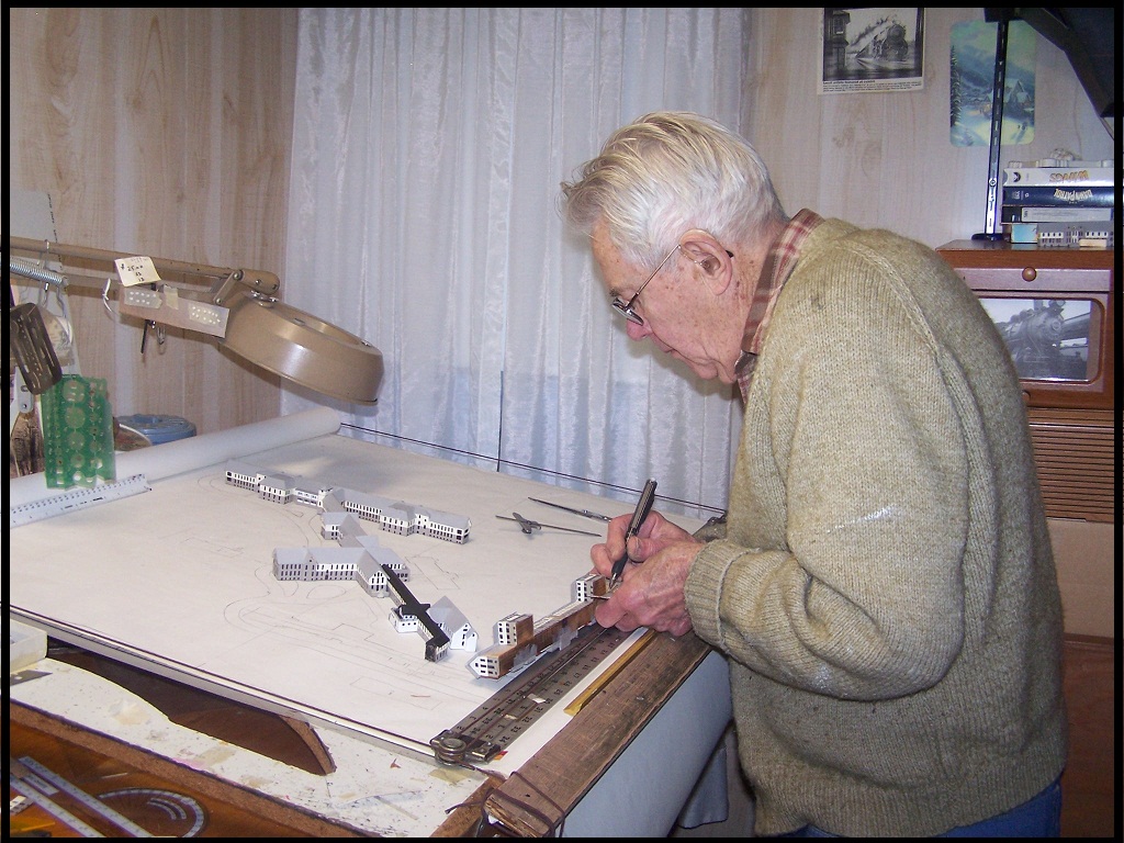
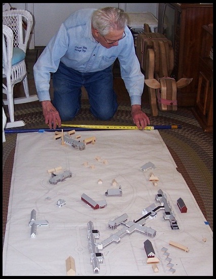
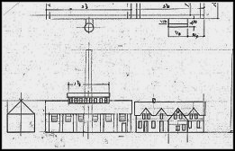
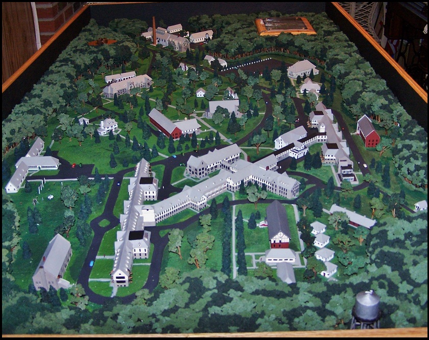
Having determined the scale of the model, dad was ready to go to the drawing board.
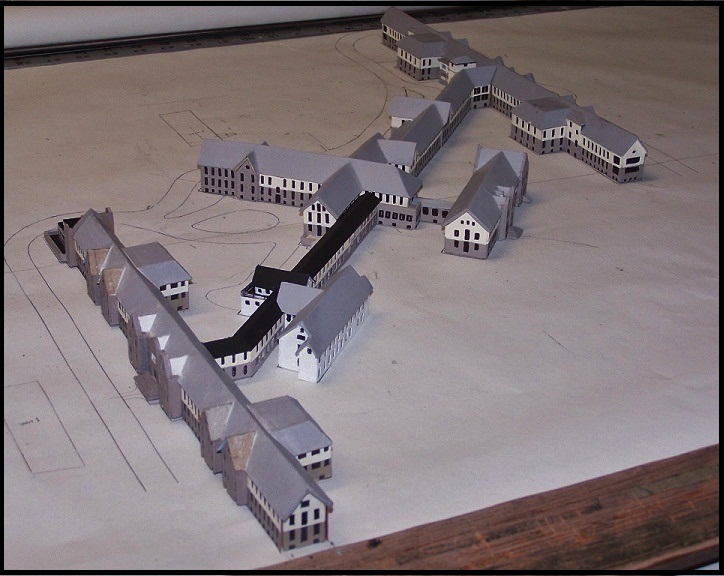
He began a full size plan that would locate all the buildings, roads, parking areas and other important features. This was
an ongoing process. Over the next several months, each new building or feature was added in its correct location and in correct
relationship to one another until the layout was complete.
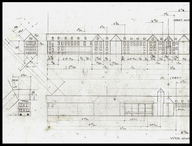
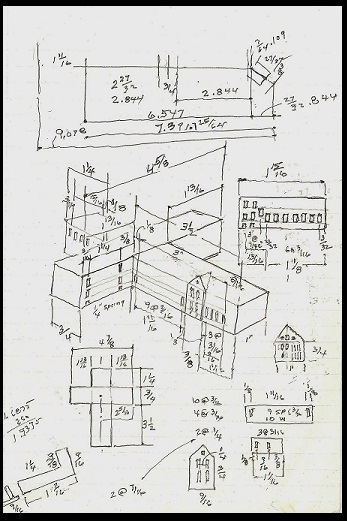
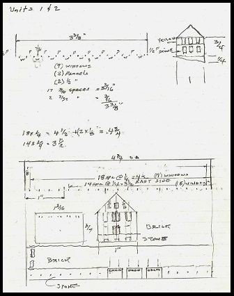
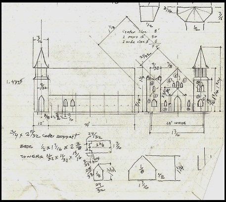
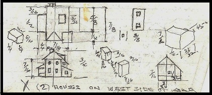
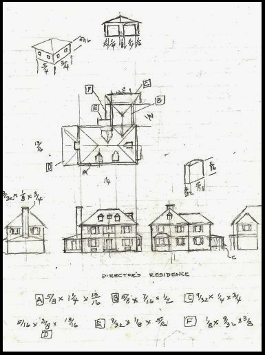
After preliminary steps to locate some of the various buildings
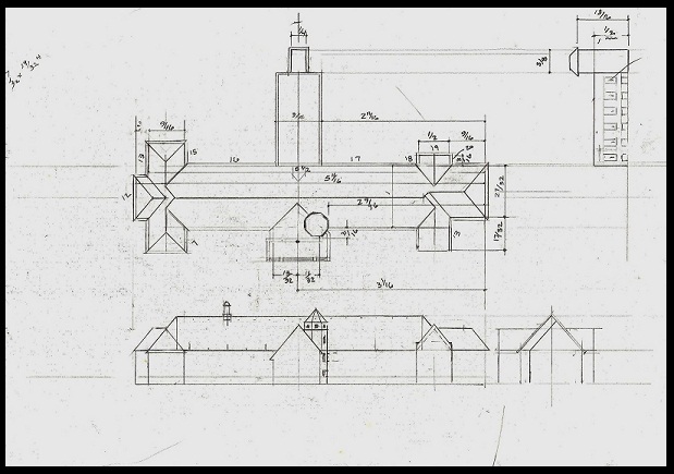
on paper, dad was ready to begin design of individual structures with regard to plan, elevation, and individual building design.
With his binder of photo enlargements, the aerial views, and information gained from my continued research, dad began detailed,
scaled drawings of individual buildings. He made every effort to represent each building as accurately as possible. Again,
without blueprints this was a monumental task. Dad had to study photos of each building thoroughly---he actually counted
the windows to help him determine building size! It was a slow, tedious process. I was continually in awe of his ability
to recognize details from those old black and white photos. His knowledge of structural design and the mechanical aspects
of the san operations (boiler works, water, etc.) were also very beneficial.
Throughout the following months, drawings
were made for each building which provided the blueprint for its construction. Dimensions were determined for all windows,
doors, porches, and other features particular to each building and added to the layout plan.
Construction
of buildings
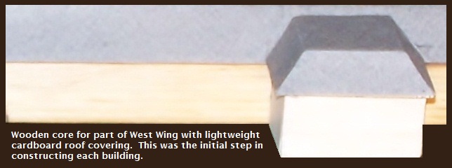
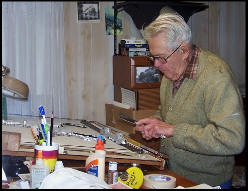
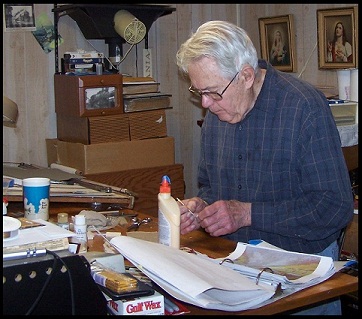
The initial construction of each building began with a solid block of wood cut to a particular
building’s dimensions. After making the basic wood core, dad measured and cut strips of .020 thick cardboard to serve
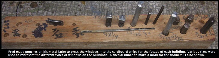
as the building façade. Next came the task of placing the windows and doors on the strips of cardboard. As there were
so many windows, I couldn’t imagine how dad would accomplish this task in a timely manner. I should have realized that
even before he made his decision to build the model, he had already formulated just such a plan. J
Over the years it has never ceased to amaze me how dad managed to create things from scratch and when he didn’t
have the tool needed to get the job done, he made it.
Once again in building the san model, he demonstrated his talent
for ingenuity. Using his the metal lathe he designed punches which would press the numerous windows located on the East and
West Wing wards and Units 1 and 2. Keeping in mind the small scale and the number of windows, this tool allowed him to maintain
window location and uniformity. The tool could be easily adjusted for individual building designs as needed.
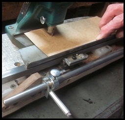
Placing
the strip of cardboard in position on the indexing/pressing tool, dad set the tool to the correct spacing and pressed the
window placement for that particular building.
Each roof was made according to its design from wood then covered with
the same .020 cardboard and putty was used to fill-in the seams. Once dry, this was sanded smooth in preparation for painting.
As required, additional pieces were made and applied, such as air vents, dormer roofs etc., following the same procedure.
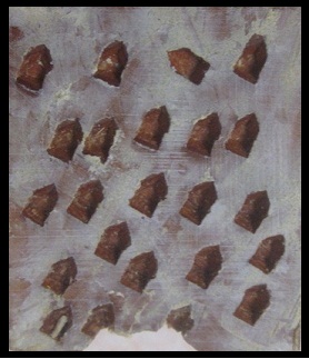
Another example of dad’s ingenuity came into play in making the many dormer windows located on some of the buildings.
These were a real challenge. Once again, he used the lathe to make a metal punch in the shape of the dormer. Next he took
a solid block of wood and pressed the punch into it to make the a number of impressions which would be the mold for the dormers.
He then mixed up an epoxy resin, filled the holes and left them to harden overnight. Each dormer window (no bigger than
a baby tooth!) would then be picked from the mold individually. Using tweezers, I then trimmed each window with a utility
blade and painted them.
As each building was made, it was then painted according to building design. Initially, dad
did the painting but with so many buildings yet to be studied, designed and constructed, this job was turned over to me. Throughout
the process, I had a hard time accepting the fact that it was neither practical nor recommended to add too much detail on
a model at such small scale. I give him much credit for his patience with me when I kept trying to come up with ways to represent
the stone/brick on the various buildings. Also for his patience the time I “messed up” and he had to press another
piece of cardboard!
To paint the buildings, first the cardboard strip had to be taped-off in order to demarcate between
the “stone” or “brick” and the “asbestos” siding. Each portion had to dry completely before
the other could be painted. Next came painting in the many windows which had been pressed into the cardboard. To accomplish
this, a fine black permanent marker was used which was very frustrating as it would become clogged by the underlying paint.
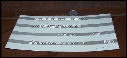
It was a slow process as each one of these small windows had to be gone over several times. Later, when working on buildings
that didn’t have as many closely spaced windows, I devised a method of using the paint application on my computer to
make windows.
After designing the individual windows, I copied rows of the various windows and printed them. Next,
I covered the rows with clear packaging tape to protect them and cut them out individually. Using these windows meant that
rather than pressing the window shapes into the cardboard, holes now had to be cut out using a utility knife. As dad made
each new building façade to scale, he began cutting the holes in the cardboard so that I could apply the windows individually
to the backside of the cardboard and affix the whole piece to the wood core for each building. The same process was used to
add doors which also were made on the computer. This method certainly didn’t speed up the process but was effective.
Dad
came up with a unique approach for depicting the church windows, as trying to depict stained glass on such a small scale was
difficult. He used individual Lactaid foil packaging and my sister recommended using various colored markers to give
a stained glass appearance. The different colors on the foil provided a good representation despite how small the windows
were!
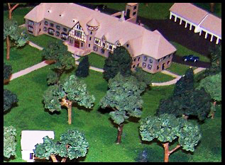
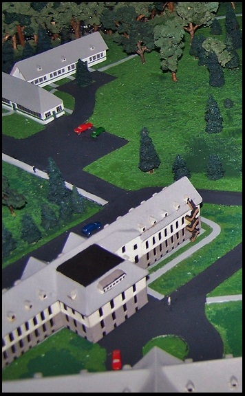
Days turned into weeks and weeks into months and slowly the san model began to take shape. Dad continued to study,
design and construct each new building which had unique features requiring special attention and planning. Throughout this
process, thought had to be given to other aspects such as the figures, trees, water towers, etc. which would add another dimension
to the model. Once again, maintaining proper scale was important. Dad determined that the figures could be no larger than
3/16² tall. I finally found figures this size at peoplescale.com and put in our order. When
they arrived, I could hardly believe how tiny they were! And each had to be hand painted! Thankfully, the vehicles were a
little easier on my eyesight.
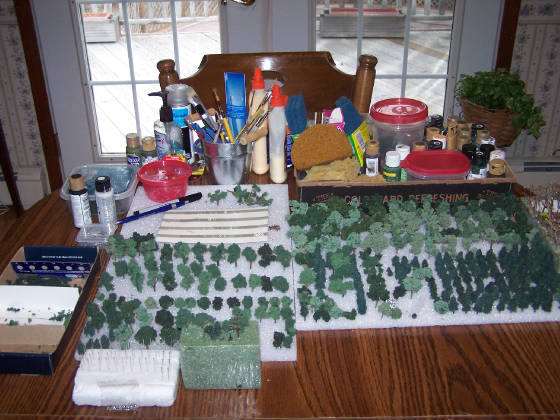
“Growing” Trees
In the
early part of the planning process, as dad was very busy with the layout/design aspects, I decided to try my hand at making
the many trees that would be needed for the model. The san, built among almost 500 acres of woodland meant that much of the
ground surrounding the facility would be wooded. Thankfully, keeping the model within a 6¢
by 3¢ finished size meant that only a representational section of woodland would be needed.
J
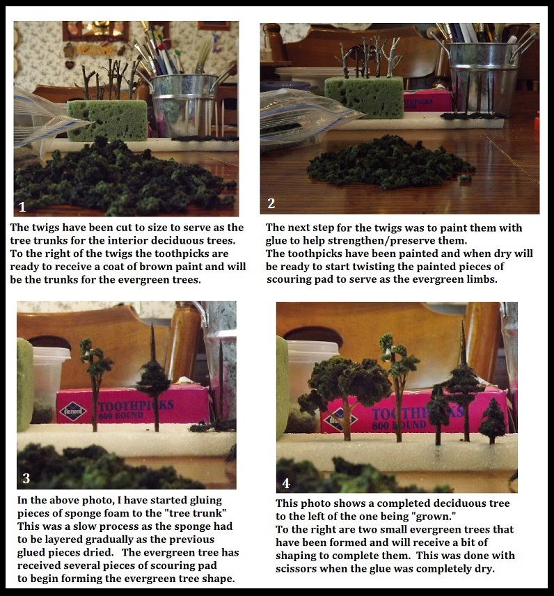
To make the trees, I walked through the woods and gathered twigs from various trees/shrubby
growth. These were used as the framework or trunk on which to “grow” the foliage. I had to keep the small scale
in mind once again, so choose only those that had small offshoots that would serve as limbs on which to attach the foliage.
These
tree frameworks were then individually trimmed to proportion and stuck into Styrofoam and painted with a clear-drying
glue thinned with water to help strengthen them. As they dried I began preparing the tree “foliage.” For this
I broke synthetic sponges into very small pieces. Thankfully, my 10 year-old granddaughter helped with this process. Over
the next few months we broke thousands of little pieces! I surprised my granddaughter later by adding her first initial
to the model using dark green “foliage” on a perimeter location. If you look closely, you just might see and “L”
among the woodland trees!
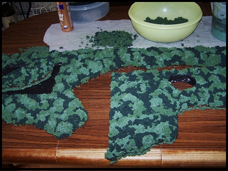
After breaking a large quantity of sponge, it was divided into several plastic containers
and I added various shades of green paint. After mixing the sponge and the paint, the excess paint was squeezed out and the
sponge was laid out on waxed paper to dry overnight. I made a small box with dividers and placed the various colors into the
different sections.
The first few trees I “grew’ were a bit too tall and dad gently reminded me of the
importance of maintaining scale. As he was otherwise pleased, he set the parameters for size and I then began my “nursery”
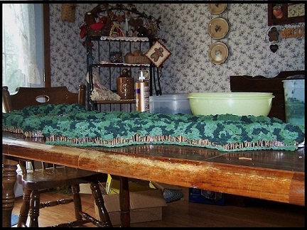
operation. I began the process of attaching the painted sponge to the small limbs of the trees. Each tree was done in stages
allowing the glue to dry, slowly layering the sponge until the tree shape took form. My dining room table soon became my “nursery”
for growing the san model trees. My husband’s standing reply when sitting down for dinner was “Oh, I see we
are picnicking in the forest again this evening!” J Dad and I were very grateful
for the support given by my mother and my husband during the many long months and our often messy, but creative efforts.
In
addition to the deciduous trees around the facility, early san patients planted thousands of evergreens on the property. As
the years passed, these lent an almost mystical quality to the landscape during the winters on Cresson’s summit. However,
this model was not representing the winter season. It sure would have made creating all those deciduous trees so much easier!
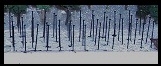
To
make the evergreen trees, I broke Scotch-Brite scouring pads into small pieces, soaked them in dark green paint,
squeezed out the excess and left them to dry overnight. Meanwhile, round toothpicks were painted dark brown and stuck into
Styrofoam to dry.
I then twisted the individual pieces of painted scouring pad onto a toothpick until I had the desired
size. Glue was placed at the top and bottom to keep the pieces in place and each trunk and branches were trimmed to shape
with scissors. Counting deciduous and evergreen, there were close to 300 interior trees made.
Building
the base
Though quite a few buildings still had to be designed and constructed, the question of a base
for the model became a priority as winter turned to spring. During this time dad juggled designing and building the base with
completing the design and building of facility structures.
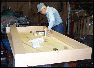
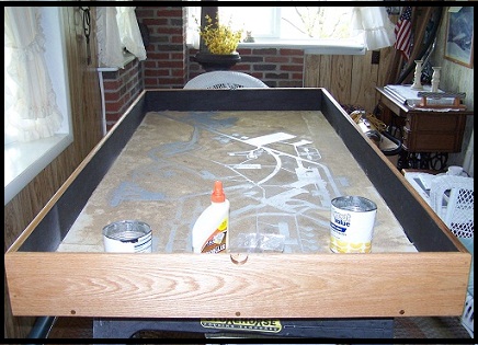
To make the base he drew up a plan then purchased ¾² plywood for the bottom and ¾² by 5 ½²
red oak boards for the sides. He mitered these at the corners and notched a recess in the top of all these boards to enable
it to receive a 3/16² thick tempered-glass which would cover the model. On each 3¢
end board, he cut a half-oval into the middle for ease in removing the glass cover if needed. Dad attached the frame by drilling,
screwing the corners and adding wooden dowel covers for the finished look. Next, the base was sanded and finished with several
coats of clear polyurethane with sanding between coats.
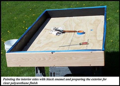
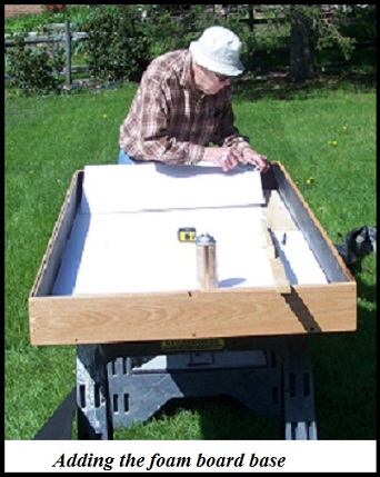
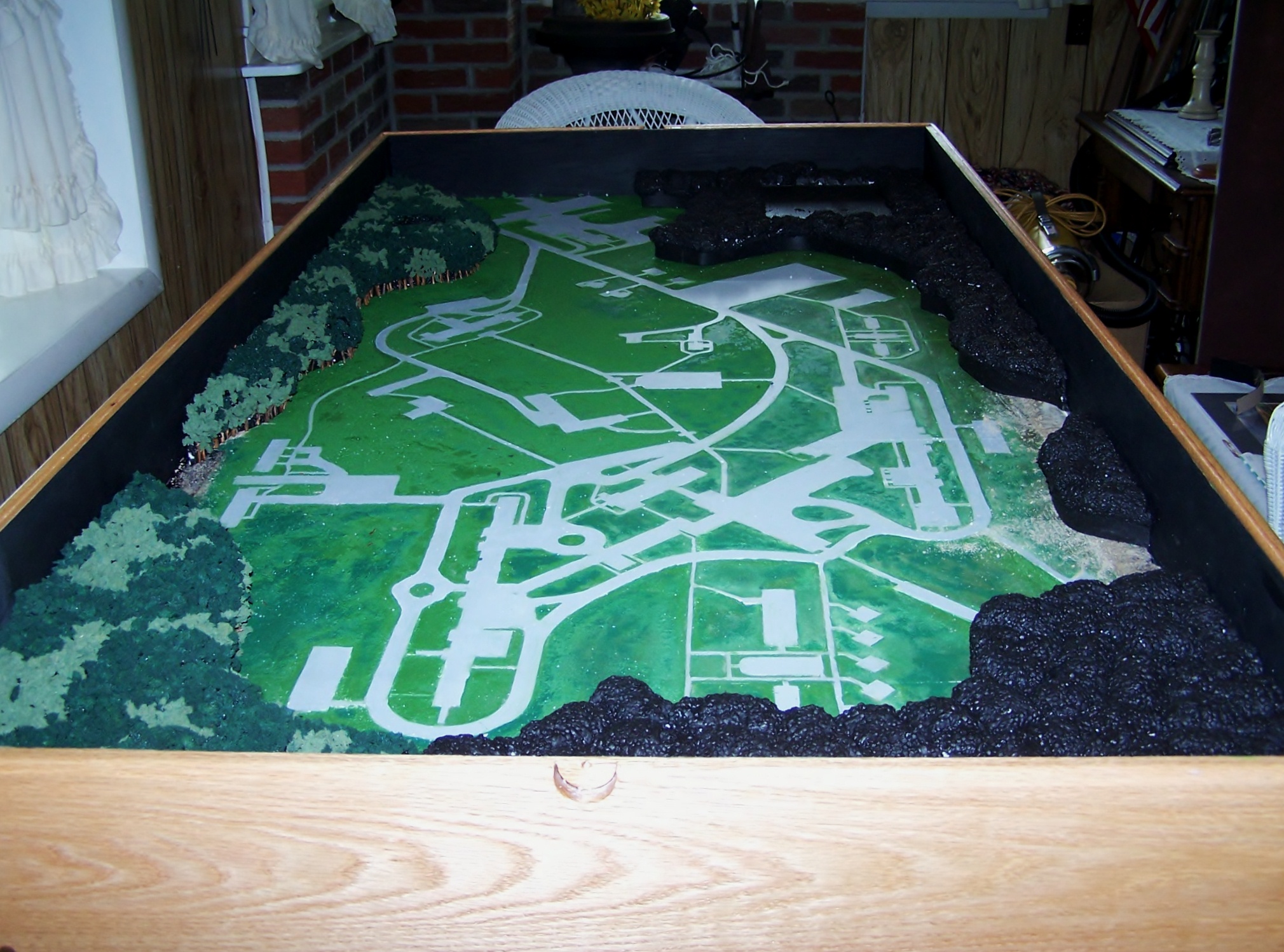
The next step was to paint the interior of the sideboard framework
with a black paint to provide contrast to the landscape and act as a wood sealant. Dad measured, cut and applied 3/16² foam board to cover the interior plywood bottom. This became the base on which dad placed the
roadways, walks, parking areas, buildings and landscaping.
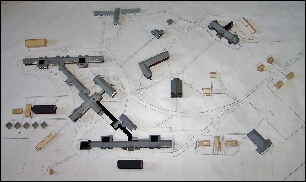
To accomplish this, dad used the layout design plan he had
worked on at the drawing board throughout the building design process. He cut out the design in sections and copied the layout
on a piece of poster paper. Next, he cut out all the roads, walks, parking areas, and building locations which were then glued
onto the foam board base in their proper location.
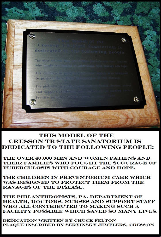
Another important aspect to consider at this time was having a dedication
plaque made.
In order to do justice to the wording on the plaque we felt that it should come from one who actually
experienced the san firsthand. Again, I turned to Chuck for help. I asked if he would write the dedication and as always,
throughout this whole process, he came through for us. We ordered the plaque from a local jeweler who graciously donated the
plaque for the model.
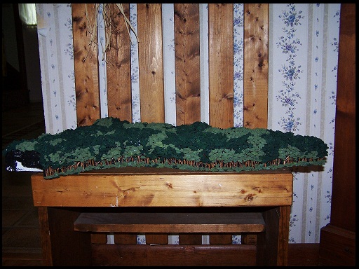
Finishing work
While dad worked on the layout transfer
and then painstakingly applied a sand/glue mixture to represent the sod, I continued making trees. Time was growing shorter
and it became apparent that the forest was growing at a slower-than-hoped-for rate. The expanse of trees still needed called
for a new plan to accomplish the goal of representing the outer perimeter woodland areas to achieve the desired effect.
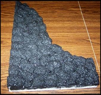
I
was shopping for supplies for the model at a local craft store when I happened to notice an employee unpacking decorative
glass jars. These jars were encased in foam packing roughly 1 ½² thick by 2¢
long by 6¢ wide. It dawned on me that this could be the answer to the question of how to go
about filling in the woodland areas. I asked if the foam packaging was being discarded and learned it was, so asked if I could
have several of them. The clerk said they were “free for the taking” so I left the store with a large bag of foam
packaging and high hopes.
I explained my idea to dad and he agreed that it should work. He made a poster paper template
for me to use to cut the perimeter shapes according to the layout plan. After marking the foam and cutting it with a utility
knife, I glued these templates onto the bottom of the foam to provide a good flat surface which would then be glued to the
foam board base.
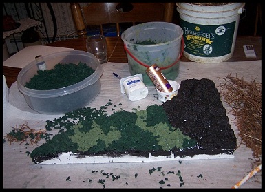
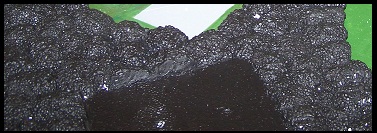
The height of the foam proved perfect for adding the sponge foliage. Initially, I intended to glue
the “foliage” pieces in layers to represent the natural peaks and valleys of a woodland setting, but dad came
up with a better plan. He took pieces of the foam that were left over and broke them into small “cloud-like” shapes.
It was painstaking work and messy…dad (and everything around him!) was covered in tiny foam balls. Dad then glued the
“clouds” to the foam pieces I had cut out to represent the perimeter woods and faced the front sections with strips
of poster paper on which the tree “trunks” would be glued. He then painted each section of foam with black sealant
paint and they were then ready to add the tree trunks representing the edge of the woodland and the foliage to represent the
forest foliage.
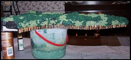
When the sections were dry I took them home to my nursery and began the process of gluing the sponge
pieces to the top of the forms and “tree trunks” to the interior facing strips. Using branches I had cut from
a small shrub beside my house, I cut them the same height as the strip and glued them in place. This was a slow process and
little did I know that this particular shrub’s branches were covered in a thin, paper-like covering which had to be
peeled and cleaned! It was a messy job and time consuming but I enjoyed the creativity involved. I layered some of the trees
for a more natural appearance and made sure some of the branches had little “limbs” on which to add “foliage.”
I even chose some that had the appearance of “knots” to add realism, though at this scale not really visible.
The black painted background helped lend an appearance of depth to the trunks and finally when all the foliage was attached
to the protruding limbs. Next the top of all the sections were covered in pieces of various shades of green sponge to represent
the variety of trees in a woodland area. These finished sections were then “transplanted” to the “Connacher
workshop” to be placed in their respective locations on the model.
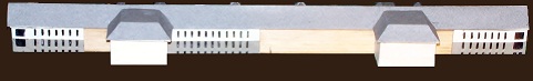
Little by little, the san model was taking
form and all the various components were coming together. It was June and there were many small but time consuming finishing
touches to be added. Dad continued designing and constructing remaining buildings and their special features such as entry
stairways, porches, vents, chimneys, etc. He also made the tiny playground equipment and even fire escapes which Dad created
by hand drawing handrails/stairs with black permanent marker on small pieces of clear plastic. Again, I couldn’t
help but marvel at dad’s creativity.
Final important details
As
I mentioned earlier, the people behind the story of the model being depicted play an important role in its construction. As
I read the stories on Chuck’s website and relayed them to dad, it was clear that a visual representation such as this
could never adequately convey the personal san experience. Fond memories shared of the native wildlife that inhabited the
san grounds stood out but on such a small scale couldn’t be depicted.
However, three features that could be represented
were the water tower, the street lights and the American Flag.
For dad and I, these three features became symbolic of
hope, recovery and unity. For at least two young men, recovery was demonstrated when they “made meals” and
began to explore beyond the confines of their Unit housing. On some excursions, they would climb the san water tower and get
a bird’s-eye-view of the surrounding countryside. In our minds, this feat became the symbol of recovery and looking
to a brighter future.
Another symbolic feature was the old acorn street lights that lined the roads and walkways. To
one little boy far from home, the light that could be seen outside his window at night became an icon in his life. Through
the seasons the glow of the light remained constant while so much of life was changing around him. We were determined to add
streetlights as a symbol of the hope that was pervasive despite the stark realities surrounding patients and staff on a daily
basis.
And of course, the American Flag that waved in front of the Administration Building. Raising and lowering this
flag was the daily duty of two brothers living in Children’s Home. The flag seemed a symbol of not only unity in a patriotic
sense but also in the unity it took to maintain a sense of normalcy for those whose lives had become anything but normal.
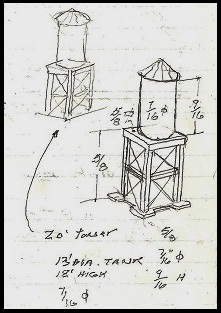
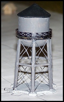
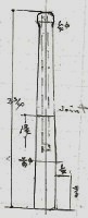
Dad set about designing the water tower from a description I found in one of the early Health Dept. journals and after
contacting Chuck about his memory of the tower. Chuck sent photo enlargements in which the tower could be seen a bit more
clearly. From these and photos of similar type water towers I found on the internet, dad designed and constructed the tower
for the model. As mentioned earlier, due to the size restrictions in building the model, the tower was moved closer to the
West Wing in order to be represented.
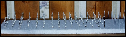
The streetlights presented a bit of a challenge once again due to the small scale
of the model. While dad worked on the tower, I made an attempt at the streetlights. Dad had to remind me that they would be
no bigger in diameter than a straight pin. I took him literally and decided a straight pin would make the perfect light pole!
First I stuck the pins in Styrofoam and sprayed them with a primer. Next I purchased tiny clear beads with a white center.
These were slid up the pin and glued to the underside of the pin head. Next I had to come up with a plan for the base. After
several experiments, I settled on using very tiny pieces of modeling clay which I rolled onto the base of the pin and shaped.
The pins were then baked to harden the clay. Finally, I painted the base, pole and top of the pin head lamppost black for
the finishing touch.
July--finishing up
After dad completed building the water tower and
it was painted, he began painting the roads and walkways as well as the “grass/sod” and began drilling holes for
the interior trees that would be placed around the buildings. I brought the trees to dad’s home from my dining room
“nursery” and he and my nephew, Rob, began the job of “planting” the trees while I worked on adding
more sponge foliage to the perimeter woodland and making a few “flower beds” and “flowering shrubs.”
Dad made and placed the playground equipment, people and vehicles on the model as well as the fire escapes. Dad also
had been busy making the wooden base for the plaque from red oak and given a clear polyurethane finish. On receiving the finished
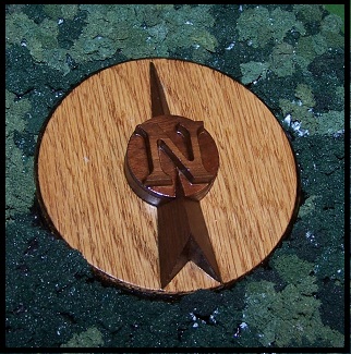
plaque from the jeweler, dad attached it to the base with screws provided. He also designed and made the directional arrow
for the model display. The arrow base was made of red oak and he used walnut for the north arrow as a contrast. As with the
model base, both of these additions were finished with clear polyurethane and attached to their respective locations among
the woodland trees on the model.
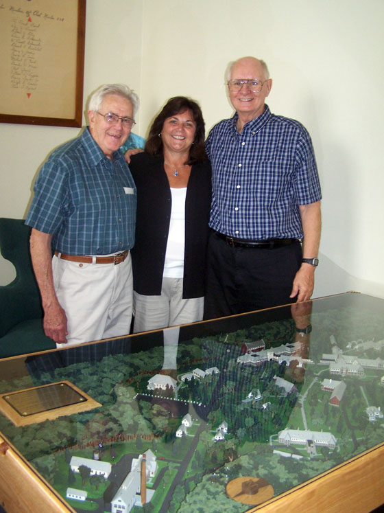
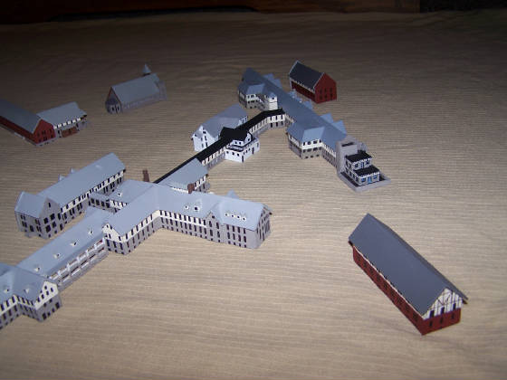
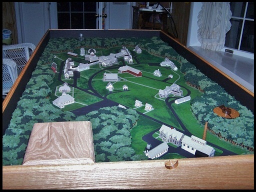
Finally in mid-July the model was at last completed and ready for the tempered-glass
cover.
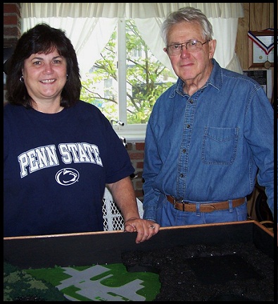
It has been difficult to describe the efforts that resulted in the building of the model of the PA State Sanatorium
at Cresson. Many, many hours went into its making. There naturally were frustrations but also plenty of humor. We often tired
from the long days, but they were hours well spent. I feel so privileged to have been a part of this project. To work alongside
my father, whom I have always admired, was priceless. It will remain a treasured memory.
Hopefully, this representation
of the PA State Tuberculosis Sanatorium at Cresson will be instrumental in preserving the memory of those who battled this
dreadful, infectious disease and all those who aided them in that effort. It’s our hope that it also serves as an education
tool and will help preserve our local history.
Our very special thanks to Chuck Felton for his support and prompt replies
to all of our questions and for those invaluable aerial photos. Also, to all those who shared their stories and photos on
Chuck’s website which made the facility much more than structures dotting the landscape.
Finally, seeing the
enjoyment of san alumni as they reminisced by the model at the 100th anniversary reunion, made all our time and
efforts worth every moment.
Theresa M. McConnell & Fred R. Connacher